Theory of Operation
The following diagram gives an example on how keymgr DPE handles multiple DICE contexts.
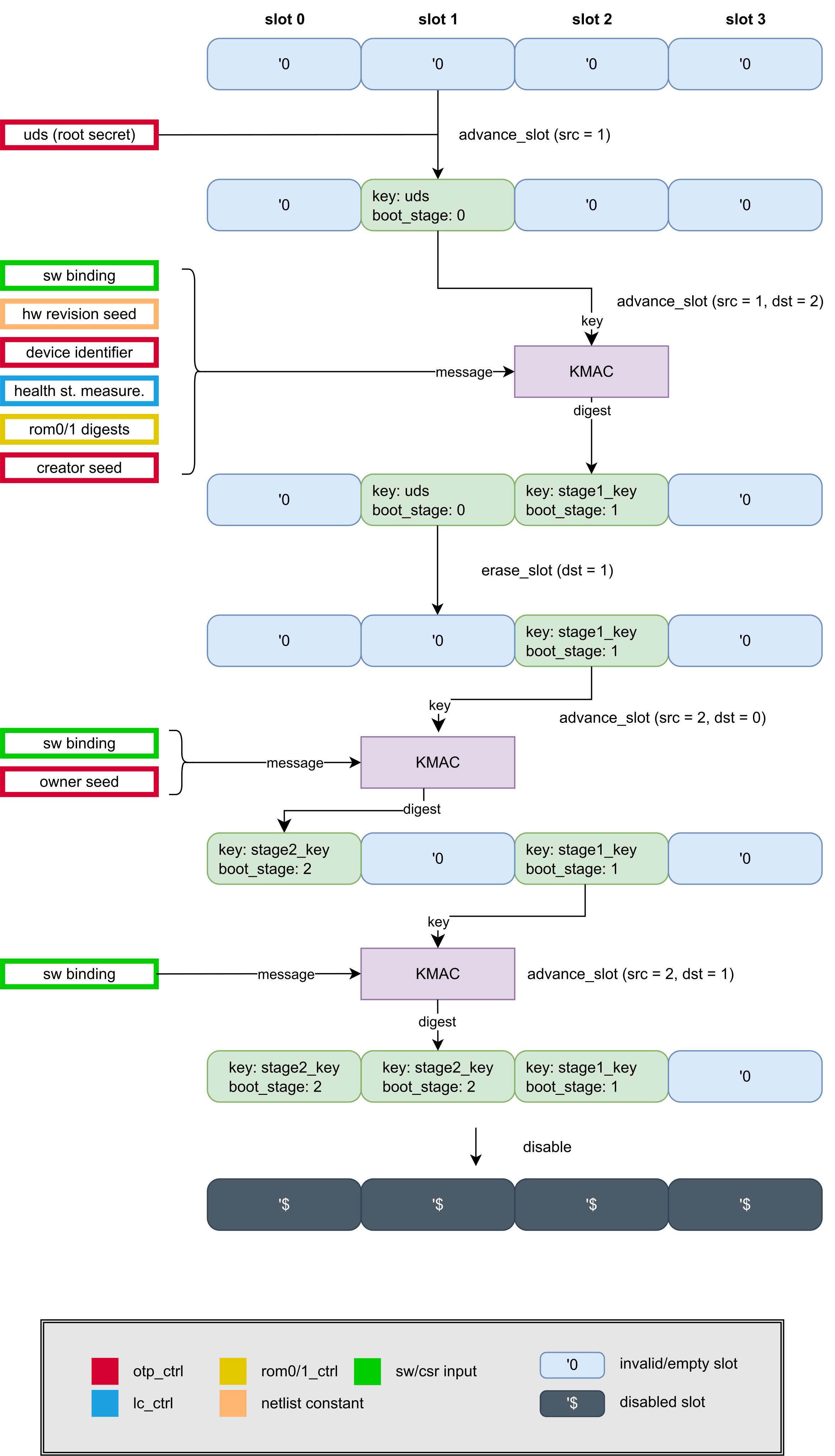
This example diagram describes a sequence of advance operations on multiple keymgr slots, assuming that keymgr_dpe is instantiated with 4 key slots. Blue rounded rectangles represent empty key slots and green color is used to denote when they become active. Each slot stores a secret key as well as context data for its key. Purple rectangles denote key derivation function (KDF) calls that are used to compute slot keys.
In OpenTitan, the KDF is instantiated as KMAC. Each valid operation involves a KMAC invocation, which uses the internal key from the selected source slot for its key input, and other HW / SW supplied inputs as its message. The concatenated components of the message is dependent on the context of the source slot as well as further inputs provided from HW / SW.
In theory, KMAC can generate outputs of arbitrary length, however this design uses a specific variant with 256-bit security strength, 512-bit digest size, and 256-bit key input.
Effectively, the key manager behavior is divided into 2 classes of functions:
-
Key manager state advancement (also referred to as deriving children slots/nodes). The resulting secrets/keys from these operations are not visible to software and not directly usable by any software controlled hardware.
-
Key generation. Results can be visible to software or accessible only by hardware (a.k.a. sideloaded keys).
For clarity, all commands issued to the key manager by software are referred to as operations.
Transactions refer to the interaction between key manager and KMAC if a valid operation is issued.
A DPE context refers to what is stored in a keymgr slot, and it consists of a secret key and its associated information.
A keymgr slot refers to the storage unit for DPE contexts, and the actual DPE context it stores is dynamically controlled by SW commands.
In order to address the relationships among keymgr_dpe slots and their stored DPE contexts more clearly, we use the terms parent slot and child slot to mean that their stored DPE contexts follow parent-child relationship in DICE hierarchy.
a || b is used to denote the concatenation of two bit strings a and b (noticeably, not the logical OR operation).
Key Manager Slots
+Keymgr_dpe consists of NumInstHwSlot slots, which is a top-level parameter (instantiated up to NumMaxHwSlot).
Each of these key manager slots can store a DPE context, i.e. all DICE-related information for a particular boot stage. That includes a secret key along with additional context information described below.
The secret key size is fixed to 256-bit.
Each slot data consists of the following fields:
validbit that tells whether the slot is occupied.boot_stageis a monotonic counter that refers to which boot stage this slot belongs to.max_key_versionstores the maximum allowed key version that is used for comparison during versioned key generation.key_policycontains policy bits that restrict advance and key generation calls that specify this slot as the source slot.
A slot is a dynamic storage unit and the DPE context it stores is controlled by SW, even though their secret keys never leave HW.
A slot becomes active (i.e. valid is set to 1) after a successful advance call that specified this slot as its destination.
When a slot is active, boot_stage refers to its DPE context boot stage.
For flexibility, boot_stage is a simple unsigned integer that is incremented from the parent’s boot_stage during advance calls.
Its actual mapping to boot stages such as ROM, BL0 or Kernel can be determined by SW.
Hence, keymgr_dpe is oblivious to this mapping between counter values and the boot stages, though with an exception.
The exception is that the initial boot stages are treated specially by RTL during KDF advance calls, as they consume other HW binding values that come from keymgr_dpe’s peripheral inputs.
From SW’s point of view, they are still treated as any arbitrary DICE layer in that SW can provide further inputs through SW_CDI_INPUT CSR.
A slot’s max_key_version receives its value from MAX_KEY_VERSION register during a previous advance call that ends up populating this slot with DPE context.
When a versioned key generation is invoked later, max_key_version field of the source slot is compared against the KEY_VERSION CSR configured by SW.
The result of this inequality check decides whether keymgr_dpe grants the request by initiating KMAC transaction that computes the requested versioned key.
Similar to max_key_version, the slot policy is not a value inherited from parent to child, but instead it is directly copied from SLOT_POLICY register into the key_policy field (again, during a previous advance call).
key_policy is the concatenation of allow_keygen || retain_parent || exportable || allow_child bits, such that:
- If
allow_childis set totrue/1, then further advance operations can be requested from this slot (assuming there are no other invalidating preconditions). Otherwise all advance requests are rejected that specify this slot as its source. exportableis currently not implemented and can be ignored.- If
retain_parentis set totrue/1, then the parent slot remains valid after an advance call. Otherwise, after the derivation of a child slot, the DPE context of the parent slot is removed automatically. - If
allow_keygenis set totrue/1, then key generation operations (both SW and sideload outputs) can be requested from this slot (assuming there are no other invalidating preconditions).
A slot populated with a root key is an exception, as neither its key_policy nor its max_key_version is taken from the corresponding CSR.
Instead, both are fixed by HW to their defaults: key_policy is set to DEFAULT_UDS_POLICY (allow_child = 1, exportable = 0, retain_parent = 0 and allow_keygen = 0) and max_key_version is set to DEFAULT_UDS_MAX_KEY_VERSION (0).
Since allow_keygen = 0, no key can be generated directly from such a slot, and SW must advance it at least once before it can generate keys.
Hence, the value of max_key_version is irrelevant for these slots.
With the exception of the secret key itself, software can read back a slot’s valid, boot_stage, max_key_version and key_policy subfields at any time through the METADATA_LOW and METADATA_HIGH registers.
Both registers are replicated NumMaxHwSlot times but only indices below NumInstHwSlot correspond to an actual hardware slot, the remaining slots are bound to 0.
METADATA_LOW.MAX_KEY_VERSION reports max_key_version, while METADATA_HIGH reports valid, boot_stage and key_policy subfields respectively.
Key Manager State
The key manager working state represents the current working state of the key manager and it is decoupled from the DICE hierarchy.
From SW point of view, keymgr_dpe’s FSM can only be in the following states: {Reset, Available, Disabled, Invalid}.
After reset, keymgr_dpe remains in Reset state until the first advance call that latches the OTP creator root key, which is also referred to as Unique Device Secret (UDS).
After this advance call, the FSM remains in Available state, and it can serve the advance/generate/erase/load requests.
Unless keymgr_dpe encounters a fault or is explicitly disabled, the FSM remains in Available state.
Invalid states such as {Reset, Invalid}, on the other hand, are used to denote out-of-operation states.
Reset
The advancement from Reset to Available internally goes through few FSM states, but from the SW point of view, this only requires a single advance call.
During these FSM transitions, the OTP creator root key is latched into a destination slot specified by SW.
The latching of the root key can only happen once until the keymgr_DPE is reset.
Until the initial advance is invoked and keymgr_DPE reaches to Available state, the key manager rejects key generation requests.
Available
During Available, keymgr_DPE accepts further advance and key generation requests.
When transitioning from Reset to Available, as a SCA counter-measure, random values obtained from the entropy source are used to populate the key slot first in a manner that both shares have the same random mask.
Then the root key is XORed on top of this randomness, in order to have fresh randomness for UDS at every power cycle.
During these transitions, keymgr_DPE’s working state will be reported as Reset, until the latching is done and keymgr_DPE is ready to accept further commands.
Disabled
Disabled is reached through an explicit disable command invocation.
In this state, keymgr_DPE is no longer operational and advance/generate/erase/load/disable commands return error.
Upon Disabled entry, the internal key slots are wiped.
However, previously generated sideload key slots and the software key stored in registers are preserved.
This allows the software to keep the last valid keys while preventing keymgr_DPE to compute further versioned keys.
Invalid
Invalid state is entered whenever key manager is deactivated through the life cycle connection or when an operation encounters a fault.
Upon Invalid entry, the internal key, the sideload key slots and the software key are all wiped.
Invalid and Disabled State
Invalid and Disabled states are functionally very similar.
The main difference between the two is how the states are reached and the entry behavior.
Disabled state is reached through intentional software commands where the sideload key slots and software key are not wiped, while Invalid state is reached through life cycle deactivation or operational faults where the internal key, sideload key slots and the software key are wiped.
This also means that only Invalid is a terminal state.
If after entering Disabled life cycle is deactivated or a fault is encountered, the same invalid entry procedure is followed to bring the system to a terminal Invalid state.
If multiple conditions happen to collide (a fault is detected at the same clock cycle SW issues disable command), the Invalid entry path always takes precedence.
Accepted Commands
During each state, there are 6 valid commands software can issue:
- Advance state
- Key generation (a.k.a versioned key generation)
- Erase slot
- Load root key
- Load secondary root key
- Disable
The software is able to select a command and trigger the key manager FSM to process one of the commands.
If a command is valid during the current working state, it is processed and acknowledged when complete.
If a command is invalid, the requested operation is rejected and the values in key slots remain unmodified.
An encoding of CONTROL_SHADOWED.OPERATION that does not map to any command is invalid in every working state.
Such a request completes immediately with OP_STATUS set to DONE_FAIL and ERR_CODE.INVALID_OP set.
More details about command interactions can be found in Programmers Guide.
Advance
Advancing a keymgr_dpe slot (also referred to as deriving a child) uses multiple inputs. Since there are multiple slots inside keymgr_dpe, source and destination parameters need to be passed to advance calls.
The very first advance call only latches the OTP creator root key (UDS), therefore most of these registers are ignored during the first call.
The only relevant registers (or register fields) during the first advance call are: CONTROL_SHADOWED.OPERATION, CONTROL_SHADOWED.SLOT_DST_SEL and START.
The fields MAX_KEY_VER_SHADOWED and SLOT_POLICY are not consumed, as the UDS slot receives the fixed defaults described in Key Manager Slots.
In particular, the destination slot for the UDS is chosen by SW, and there is no designated special slot for it.
Moreover, since the destination slot for this first advance call has no parent, its boot_stage value is not incremented but initialized to 0.
This initial latching can be repeated with the Load Root Key operation unless locked with the LOAD_ROOT_KEY_LOCK register.
If the OTP creator root key is not valid during the latching cycle, keymgr_dpe moves to Invalid state.
Further advance calls use the key stored in the specified CONTROL_SHADOWED.SLOT_SRC_SEL slot (equally referred to as parent or source slot) , and the result of the derivation updates the slot specified by CONTROL_SHADOWED.SLOT_DST_SEL (referred to as destination or child slot).
Assuming that key_policy, boot_stage or valid bits of the parent context permit, the child secret is derived from the parent secret through a key derivation function during advance operation.
child_key = KDF(parent_key, message), where the message input takes different forms depending on the parent slot’s boot_stage value.
Which HW binding values are consumed at each stage is controlled by the NumBootStages parameter, and in particular whether the creator_seed is consumed together with the other creator inputs (two-stage configuration) or by a dedicated intermediate owner stage (three-stage configuration).
See KDF Details for more details on HW binding values.
With NumBootStages = 3, the creator_seed is consumed by a dedicated OwnerInt (owner intermediate) stage:
- If
boot_stage = 0(Creator) for the parent, thenmessage = SW_CDI_INPUT || device_identifier || health_st_measurement || rom_descriptors || hw_revision_seed. - If
boot_stage = 1(OwnerInt) for the parent, thenmessage = SW_CDI_INPUT || creator_seed. - If
boot_stage = 2(Owner) for the parent, thenmessage = SW_CDI_INPUT || owner_seed. - If
boot_stage > 2for the parent, thenmessage = SW_CDI_INPUT.
With NumBootStages = 2, the OwnerInt stage is omitted; the creator_seed is consumed together with the other creator inputs, and an advance from Creator increments boot_stage directly to Owner (i.e. boot_stage = 1 is not used):
- If
boot_stage = 0(Creator) for the parent, thenmessage = SW_CDI_INPUT || hw_revision_seed || device_identifier || health_st_measurement || rom_descriptors || creator_seed. - If
boot_stage = 2(Owner) for the parent, thenmessage = SW_CDI_INPUT || owner_seed. - If
boot_stage > 2for the parent, thenmessage = SW_CDI_INPUT.
Regardless of boot_stage, software can force an advance call to use only message = SW_CDI_INPUT (dropping HW binding values) by setting CONTROL_SHADOWED.SW_BINDING_ONLY.
To prevent a later boot_stage from clearing this option to maliciously reconstruct earlier keys, the ENFORCE_SW_BINDING register locks this behavior.
Once set, every subsequent advance call from a parent with boot_stage <= 2 (i.e. a stage that would consume HW binding values) must use SW_BINDING_ONLY, permanently blocking access to HW binding values until the next reset.
Advance calls from parents with boot_stage > 2 are not affected, as their message is SW_CDI_INPUT regardless of SW_BINDING_ONLY.
At the end of a successful advance operation, the following updates are made for the slot selected by SLOT_DST_SEL:
validbit is set to 1.key_policyis updated withSLOT_POLICY.max_key_versionis updated withMAX_KEY_VERSION.boot_stageis set to the parent’sboot_stage + 1, except for the initialAdvancecall that initializes the UDS slotboot_stagevalue to0.keyis updated from the key received from KMAC.
Whether the same slot can be chosen both as the source and the destination during advance call depends on retain_parent policy bit.
If retain_parent is set, then the advance operation must provide different source and destination slots.
If retain_parent is set to false/0, then the source and destination slots must be the same.
In other words, retain_parent = false forces SW to request in-place update, which automatically removes the parent’s DPE context.
When there is no fault and the enable signal is active by life cycle controller, the validity of an advance operation is defined as follows:
- If keymgr_dpe is in
Resetstate (i.e. the first advance call that latches UDS), then an advance operation is valid if all of the following conditions are satisfied (AND clause):CONTROL_SHADOWED.SLOT_DST_SELis belowNumInstHwSlot.- The OTP creator root key is valid during the clock cycle keymgr_DPE tries to latch it.
- If keymgr_dpe is in
Availablestate, then an advance operation is valid if all of the following conditions are satisfied (AND clause):- Keymgr_DPE is in
Availablestate. CONTROL_SHADOWED.SLOT_SRC_SELandCONTROL_SHADOWED.SLOT_DST_SELare both belowNumInstHwSlot.valid = truefor the source slot.allow_child = truefor the source slot.- If
retain_parent = true, then the source and the destination slots are different. - If
retain_parent = true, then the destination slot is not valid (i.e.valid = 0). - If
retain_parent = false, then the source and the destination slots are the same. boot_stageof the source slot has not reached to the maximum value supported by HW (i.e.boot_stage + 1 < NumBootStages).- If
ENFORCE_SW_BINDING.ENFORCEis set and the source slot hasboot_stage <= 2, thenCONTROL_SHADOWED.SW_BINDING_ONLYmust also be set.
- Keymgr_DPE is in
Versioned Key Generation
A versioned key generation operation uses the following registers:
CONTROL_SHADOWED.DST_SELdetermines the target use for the generated key, and that is either one of {AES,KMAC,OTBN,HMAC}.CONTROL_SHADOWED.SLOT_SRC_SELdetermines the source slot whose key should be used for the key derivation.SALTis used as a part of the message during the key derivation.KEY_VERSIONis the target key value, and it also becomes the part of the message for KDF call.
During the generate operation, a versioned key is generated from the secret of the source slot selected by SLOT_SRC_SEL.
After a successful key generation operation, if the generated key is requested for HW use, then the generated key is loaded into the sideload slot that drives the specified target peripheral port (DST_SEL being either one of {AES, KMAC, OTBN, HMAC}).
In the case of SW key, the generated key is loaded into a CSR (see SW_SHARE0_OUTPUT and SW_SHARE1_OUTPUT registers).
The key is generated with a KDF call, where the secret key is read from source slot.
Then, generated_key = KDF(parent_key, KEY_VERSION || SALT || dest_seed || output_key) where dest_seed and output_key are domain separators (i.e. diversification values from netlist) to distinguish SW/HW outputs as well as the target HWIP peripheral {AES, KMAC, OTBN, HMAC}.
KDF used for key generation calls is the same KMAC instance used in advance calls.
The only difference is that the input messages are 0-padded to another length parameter, GenDataWidth.
Key generation request is valid if all of the following conditions are satisfied (AND clause):
- The internal FSM is in
Availablestate. Namely, keymgr_dpe rejects key generation requests duringInvalid/Disabledas they are inactive states, and duringResetfor not having latched the UDS key yet. - The selected source slot is below
NumInstHwSlot. - The selected source slot is valid.
allow_keygen = truefor the source slot.KEY_VERSIONis less than or equal tomax_key_versionof the source slot.DEST_SELcontains one of the five valid sideload destinations (None, AES, KMAC, OTBN, HMAC).
Erase slot
Erasing operation can be used to clear the DICE context from a destination slot. This is done by selecting the slot with CONTROL_SHADOWED.SLOT_DST_SEL, and then configuring and initiating the operation. At the end of a successful erase, the DPE context is removed from the destination slot.
Note that the slots with retain_parent = false policy do not require explicit erase calls, as they are automatically erased when advanced.
However, HW does not specifically block such an erase request.
Meanwhile, the slots with retain_parent = true can only be destroyed with explicit erase calls, as advance calls will reject overwriting these slots.
Erase request is valid if the following conditions are satisfied:
CONTROL_SHADOWED.SLOT_DST_SELis belowNumInstHwSlot.- The destination slot is valid (i.e. not empty).
- keymgr_dpe FSM’s working state is
Available.
Load Root Key and Load Secondary Root Key
keymgr_dpe can hold two independent root secrets, from which separate DICE hierarchies can be derived:
- The creator root key, which is latched by the first advance call and can be loaded by an explicit software request.
- The secondary root key, which is only loaded on an explicit software request.
The secondary root key is intended as an additional, independent root secret that anchors a second DICE hierarchy, i.e. a separate chain of derived keys and attestation identities. This allows software to keep the two hierarchies isolated from each other, for example to attest a different identity chain without exposing the primary one.
See Root Keys for where these secrets come from.
The Load Root Key and Load Secondary Root Key operations load the respective root key into the slot selected by CONTROL_SHADOWED.SLOT_DST_SEL.
Apart from the secret that is loaded, both operations behave identically.
They do not involve a KMAC transaction and complete within a single cycle.
At the end of a successful load operation, the following updates are made for the destination slot:
validbit is set to 1.boot_stageis initialized to0(Creator).max_key_versionis set to the defaultDEFAULT_UDS_MAX_KEY_VERSION, independent ofMAX_KEY_VER_SHADOWED.key_policyis set to the defaultDEFAULT_UDS_POLICY(allow_child = 1,retain_parent = 0,allow_keygen = 0,exportable = 0), independent ofSLOT_POLICY.keyis updated with the root key: each share of the root key is XORed on top of the corresponding share of the slot’skeyfield.
All fields other than key are overwritten, i.e. none of the previous DPE context information is retained.
A load request is valid if all of the following conditions are satisfied:
- keymgr_dpe FSM’s working state is
Available. CONTROL_SHADOWED.SLOT_DST_SELis belowNumInstHwSlot.- The destination slot is not valid.
- The respective root key is marked valid by its source.
- The operation is not locked through
LOAD_ROOT_KEY_LOCKorLOAD_SECONDARY_ROOT_KEY_LOCKrespectively.
LOAD_ROOT_KEY_LOCK and LOAD_SECONDARY_ROOT_KEY_LOCK are write-1-to-set registers that remain set until the next reset.
Software is expected to set them once the respective root key is no longer needed in the current boot, so that later boot stages cannot reload it.
If the respective root key is not valid when a load operation is started, DEBUG.INVALID_ROOT_KEY or DEBUG.INVALID_SECONDARY_ROOT_KEY is set.
DEBUG.INVALID_ROOT_KEY is additionally updated when the creator root key is latched by the first advance call.
Disable
Disable operation simply moves the keymgr_DPE’s FSM into Disabled state. This operation request is valid only if the FSM is in Available state.
Peripheral Connections
Root Keys
keymgr_dpe receives two 256-bit root secrets, each provided in two shares with a valid bit per share:
creator_root_keyis the creator root key received from OTP.secondary_root_keyis the (optional) secondary root key. Its source depends on the integration, for example OTP on Earl Grey.
The valid bits of both root keys are synchronized into the keymgr_dpe clock domain before use.
KDF Details
KDF used for advance calls is the KMAC instance with (keylen=256, digest_len=512, sec_lvl = 256) parameters. The input messages to KDF are always 0-padded to the fixed length specified below.
During advance operations, KDF inputs are 0 padded to AdvDataWidth bits. Depending on the boot stage, KDF message input also receives the following inputs:
hw_revision_seedis a 256-bit netlist constant.device_identifieris a 256-bit non-secret device identifier. This value is received from peripheral OTP port.health_st_measurementis a 128-bit domain separator (i.e. diversification constant) that depends on the life cycle stage. This value is received from peripheral LC port.rom_descriptorsareNumRomDigestInputshash values received from the respective ROM controller(s). Each digest is 256-bits.creator_seedis 256-bit creator secret received from theSECRET2OTP partition..owner_seedis 256-bit owner secret received from theSECRET3OTP partition.
During key generation operations, KDF inputs are 0 padded to GenDataWidth bits. Some diversification constants are:
dest_seedis a 256-bit diversification value for each cryptographic key type {AES, KMAC, OTBN, HMAC}.output_keyis a 256-bit diversification value for distinguishing software and sideload keys.
Life Cycle Connection
The function of the key manager is directly managed by the life cycle controller.
Until the life cycle controller activates the key manager, the key manager does not accept any software commands. Once the key manager is activated by the life cycle controller, it is then allowed to transition to the various states previously described.
When the life cycle controller deactivates the key manager, the key manager transitions to the Invalid state.